|
I'd like to discuss the current status of our spectroscopy amplifier development.
Currently, we offer custom-made systems integrating amplifiers with restricted
specifications for sale. However, we have not yet launched Techno AP's
spectroscoy amplifiers.
This decision does not reflect a policy against selling spectroscopy amplifiers,
as our flagship products are DSPs. Rather, the challenge lies in our ongoing
efforts to develop spectroscopy-grade products that match the performance
standards required for HPGe without compromise. The images below depict
remnants of our development process. The term "rev 10" signifies
that we have attempted development ten times, encountering setbacks along
the way.
|
|
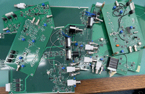
Fig. 1
|
|
Nowadays, DSP technology is thriving in radiation measurement. There is
skepticism about whether commercializing a spectroscopy amplifier at this
moment would yield sufficient profitability to recover development costs.
However, as a manufacturer specializing in radiation measurement circuits,
I believe that adding a spectroscopy amplifier to our product lineup will
become a necessity.
Finally, this year, our prototype has achieved satisfactory performance,
paving the way for future commercialization. At the outset of development,
I approached the design of the spectroscopy amplifier available on the
market with the notion that updating it with modern ICs could easily surpass
or match its performance from the 1980s. However, the initial prototype
fell short, as the IC did not meet expectations, compounded by gaps in
our understanding leading to its rejection. Subsequent attempts to prototype
were met with repeated failures over the years. The process was so tumultuous
that recalling the specific issues becomes a challenge in itself.
Meanwhile, while actively advancing our DSP development, we also steadily gained expertise in amplifier technologies. Eventually, I chose to focus on three critical areas and address them sequentially:
(1) Mastering the design of Gaussian shaping using the active filter module.
(2) Refining the optimization of the baseline restorer.
(3) Developing a hybrid amplifier circuit with low noise.
Today, I will delve into the first point. The typical Gaussian shaping
circuit employing the active filter module comprises an initial stage featuring
a differentiation circuit with adjustable poles and zeros, followed by
a fourth-order integration circuit incorporating an intermediate amplifier,
illustrated in Figure 2.
|
|

Fig. 2 Gaussian shaping circuit
|
|
The S/N of complete Gaussian shaping is 1.12, and the Laplace transformed equation becomes Eq. (1), but it is impossible to integrate over an infinite range.
|
|

Eq. (1)
|
|
An active filter with an S/N ratio of 1.14 has parameters k1 and k2 that indicate the sharpness of the filter,
but k1 and k2 can be adjusted by shifting the time constant of τ = RC.
Eq. (2) is a Laplace transformed equation.
|
|

Eq. (2)
|
|
Set the time constants of τ = RC of the four-time integration circuit together at four locations.
It becomes simple as Eq. (3).
|
|

Eq. (3)
|
|
This circuit also achieves an S/N ratio of 1.17, making it a cost-effective
design. It utilizes the single-differential, four-time integration method.
To simulate the waveform generated by this circuit on a PC, we perform an inverse Laplace transform to convert it into a time-domain function.
For this task, we employ Maxima, a formula processing software originally
developed at the Massachusetts Institute of Technology (MIT).
Maxima is capable of outputting formulas for various mathematical operations
such as simultaneous equations, differential and integral calculus, differential
equations, and Laplace transforms, similar to what is required in this
instance. Formulas copied from Maxima can be directly pasted into C language
format.
Maxima proves highly valuable for application developers like our company, offering robust functionality at no cost. Figure 3 depicts the time function obtained by inverse Laplace transforming Eq. (3) with a unit step input.
|
|
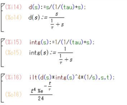
Fig. 3 Maxima Laplace inverse transform differential and integral calculus4
|
|
Fig.4 is a time function obtained by applying Laplace transform to Eq.(2), giving a unit step input, and performing the inverse Laplace transform.
The formula is quite complicated, but you can easily code it by copying and pasting.
|
|
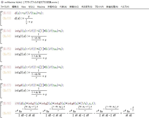
Fig. 4 Maxima Laplace Inverse Transform Active Filter
|
|
Since it is a time function, if you give t, it will become a waveform.
In the active filter method, the key is whether the optimal solution for
k1 and k2 can be derived.
In Fig. 5, the time constant is 1μs. The active filter method returns to the baseline faster.
|
|
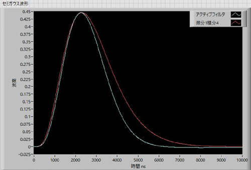
Fig. 5 Comparative simulation of active filter and differential calculus 4
|
|
Fig. 6 shows a comparison of the prototype using an oscilloscope.
The time constant is 6μs. It's almost the same as the simulation.
|
|
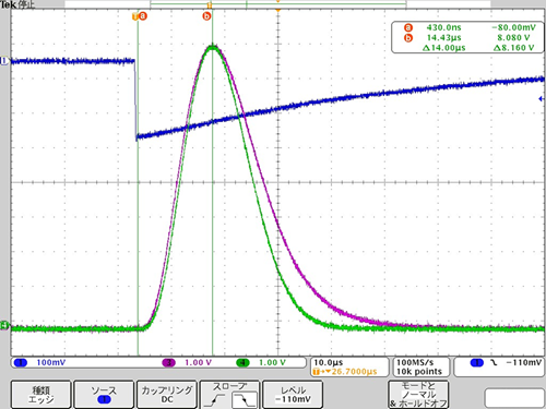
Fig. 6 Actual measurement in circuit
|
|
Fig. 7 shows an enlarged view around the baseline.
The active filter method appears to be more advantageous as the counting rate increases.
|
|
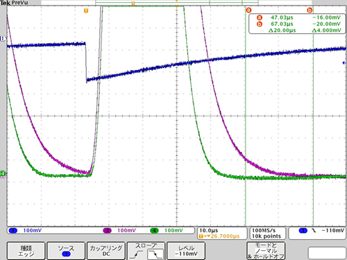
Fig. 7 Scope near baseline
|
|
Now, connect the prototype to the MCA and measure the spectrum.
Here, we focused on the Gaussian shaping method and evaluated it by varying
the resistor and capacitor values for comparison. The baseline restorer
and low-noise amplification circuit are optimized, and waveform shaping
methods are compared.
Fig. 8 shows the spectrum obtained using the active filter method.
|
|
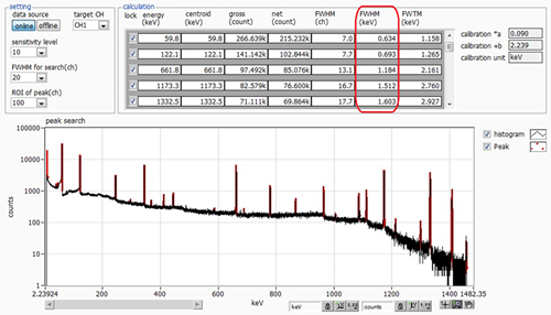
Fig. 8 γ-ray spectrum obtained using the active filter method
|
|
Fig. 9 shows the spectrum obtained using the one-differential, four-time integration method.
The resolution is slightly worse than that of the active filter method with the low-energy side being particularly poor.
|
|
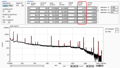
Fig. 9 Differential integration 4 gamma ray spectrum
|
|
It has become clear that there is a significant performance difference that cannot be overlooked.
After thoroughly understanding and designing the active filter method, we finally reached a breakthrough. I will address other points at a later time.
In the future, we plan to develop amplifier products such as the standard NIM 1ch version, 8ch or 16ch multichannel versions.
We are also considering the development of a spectrometer that integrates an amplifier, MCA, and high-voltage power supply.
Our entire team is committed to creating even better products moving forward.
Thank you very much for your continued support.
|