|
 |
Digital Signal Processor [Applicable Models] APV (U) 8002X, APV (U) 8004X, APV (U) 8008X, APV (U) 8016X APN (U) 502X, APN (U) 504X |
| Q1 | "Connection error" dialog box is displayed when starting the attached application, and the computer and the device can not be connected. |
| A1 | Please refer to "Ethernet". |
| Top |
| Q2 | Do you have the recommended settings? |
| A2 | Please refer to "Configuration Reference". NOTE: The content of setting varies depending on the type and polarity of the detector, importance on energy resolution capability or emphasis on counting. |
| Top |
| Q3 | Do you offer sample programs? |
| A3 | For now we offer sample programs only for a few products. Please download from this page and use it.. The development language is Visual C ++, Visual C #, Linux, LabVIEW.. |
| Top |
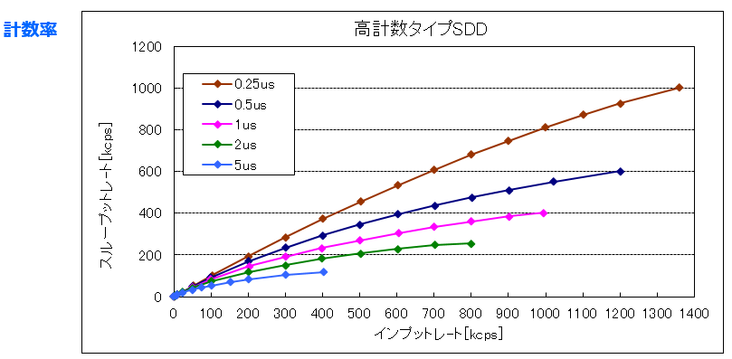
| Q4 | It seems that energy resolution is bad... |
| A4 | As an example of the DSP for x-ray measurement, we confirmed that
it has the performance as shown below in relation between 5.9 keV (Mn -
Kα) resolution and count rate.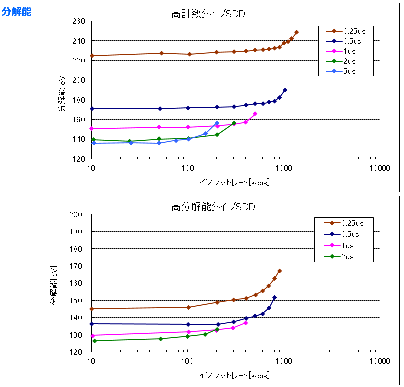 The higher the count rate, the worse the energy resolution becomes. As shown above, if the peaking time is increased to 2 μs or 5 μs, good energy resolution can be obtained if the count rate is low, but as the counting rate increases the energy resolution can not be maintained. On the other hand, if the peaking time is shortened to 0.25 μs, the energy resolution is lowered even when the count rate is low, but its energy resolution is maintained to some extent even if the counting rate increases. If the energy resolution is bad, please check the following. Please refer to the hardware manual and software manual for details. 1. The power supply of the DSP is taken from the same tap supplying the preamplifier power of the detector. 2. There are no equipment near the DSP that will become a noise generation source like a refrigerator or inverter. 3. Do not bring the preamplifier output signal cable of the detector close to the power cable of AC100V. Also, there is no equipment such as a computer power adapter near the cable as a noise source. 4. The setting of the gain of the preamplifier output signal captured inside the DSP is appropriate. Connect the "MONI" output terminal to the oscilloscope with a cable, set the DAC type of the attached application as "preamp", the signal is within the upper limit 1 V and the influence of noise is minimal. Also, the pole zero is properly adjusted. 5. "Analog trigger threshold" setting is appropriate. Start measurement and find the boundary with the noise level while looking at the value of "input total rate". In the case of the noise level, the value becomes extremely large. If you raise the set value gradually, the noise will not come out. Set a value that is slightly higher than the noise level setting. 6. "Slow trigger threshold" setting is appropriate. Start measurement and confirm that "input total rate" is not extremely high count due to noise influence. Next, look at the value of "throughput rate" and find the boundary with the noise level. In the case of the noise level, the value becomes extremely large. If you raise the set value gradually, the noise will not come out. Set a value that is slightly higher than the noise level setting. 7. The waveform shaping (filtering) signal inside the DSP is appropriate. Connect the "MONI" output terminal to the oscilloscope with a cable, set the DAC type of the attached application to "slow", and that signal is properly adjusted within the range of 1 V upper limit. 8. If there are variations in the rising edge of the preamplifier output waveform, such as germanium semiconductor detector, set the value of "slow flattop time" to twice the rise time considered to be the slowest. 9. High voltage power supply to the detector is not appropriate. Also check the rated voltage, ripple, cable and so on. . 10. Power supply to the preamplifier power supply is not appropriate. |
| Top |
| Top |
Copyright (C) TechnoAP All Right Reserved.
Last Update: 5, July, 2018.
Last Update: 5, July, 2018.